
Electronics Foundations — Validating Sensor Inputs
The Voltage Dropped When the Sensor Was Connected
In one line
The output of a voltage divider is not determined by the resistor ratio alone. Whatever you connect to the output is also part of the circuit.
Why this was needed
Suppose you want to read a 5 V sensor and you halve the voltage with two resistors of the same size. You calculated 2.5 V with nothing connected, but when you connect another circuit, the value drops. Before fixing the sensor driver, you have to ask whether the circuit is still the same circuit. This course is not about how to build a power supply that regulates voltage; it is about how to calculate the loading effect on a signal input.
Voltage is the difference between two points, and here every output is a value relative to ground. The unit of current is A, resistance is Ω, and power is W. 10 kΩ is 10,000 Ω and 1 mA is 0.001 A. You must record the units of voltage and current together to catch a mistake where the power is off by a factor of a thousand.
How it works
There is Rtop between the supply and the output, and Rbottom between the output and ground. If you add Rload from the output to ground, the bottom resistor and the load become parallel.
Vin ── Rtop ──┬── Vout
              ├── Rbottom ── GND
              └── Rload   ── GND
With no load, Vout=Vin*Rbottom/(Rtop+Rbottom). With a load, replace the bottom resistor with Rp=1/(1/Rbottom+1/Rload). Written in terms of current, the same thing is (Vin-Vout)/Rtop=Vout/Rbottom+Vout/Rload. This is conservation of charge: the current flowing into a node equals the current flowing out of it. If you leave out the load current on the right, the form looks fine but you have calculated a different circuit.
Try a different example with Vin=6 V, 2 kΩ top and bottom, and a 4 kΩ load. With no load it is 3 V, and after connecting it is 2.4 V. Even though the voltage falls, the current flowing from the supply increases from 1.5 mA to 1.8 mA. The guess that it consumes less because the output went down is wrong.
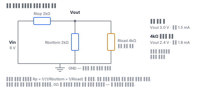
The power is the square of the voltage across each resistor divided by its resistance. For the top resistor use Vin-Vout, and for the bottom resistor and the load use Vout. In an ideal static circuit, the sum of the three consumed powers must equal the supply voltage × the supply current. If you calculate these two ledgers separately, you can catch mistakes such as wrongly combining resistors in parallel or getting units wrong.
What it looks like in the field
An ADC input is not always a single fixed resistor. Because of input leakage, the sampling switch, and the capacitor, a static load model alone cannot guarantee the real accuracy. This model is meant for learning the loading effect in isolation. When you connect a multimeter, you must also check its input impedance.
NVIDIA's board development role asks for board failure root cause analysis and validation planning. This calculation is an entry-level step toward that skill and does not replace the whole of that experienced-hire job. The hiring basis is the official posting checked on 2026-09-10. It is the posting content seen in a search index, and whether it can currently be applied for has not been confirmed.
The habit of drawing the measurement points first
Before asking how many volts, draw the reference point and the connections between the parts. Measuring the voltage across the top resistor is different from measuring from the output to ground. In the 6 V example above, the top voltage is 3.6 V and the bottom is 2.4 V. Adding the two values must bring you back to the supply voltage of 6 V. This is why you check currents at a node and voltages along a closed path.
Let's also calculate the power of the same example. The top is 3.6²/2000=0.00648 W, the bottom is 2.4²/2000=0.00288 W, and the load is 2.4²/4000=0.00144 W. The total is 0.0108 W, and the supply delivers 6×0.0018=0.0108 W. If you wrongly put 2.4 V on the top resistor, this sum does not balance. The habit of checking whether different conservation laws give the same answer lasts longer than memorizing the answer to a single formula.
If the load resistance is very large, the parallel combination approaches the original bottom resistor and you return to the no-load result. Conversely, as the load approaches 0 Ω, the output falls toward ground. If you wrote code, test these two limits. If you make the load smaller and the output gets bigger, you have probably written the parallel formula upside down. A limit check covers a wider range of conditions than hitting one arbitrary number.
If you make the two divider resistors 10 times smaller, the divider may be less shaken by the same load, but the no-load current becomes 10 times larger. For a sensor where battery life matters, a smaller resistor is not always better. There is the alternative of adding a buffer amplifier, but that adds reviews of the supply, the input and output range, the offset, and stability. You should write the goals in two slots, such as "reduce loading error" and "reduce supply current", for the trade-off to show.
This ideal supply assumes an internal resistance of 0. If the output resistance of a real sensor is known, you must add it to the top path. Do not quietly treat an unknown value as 0; leave it as an unconfirmed item and as a datasheet item to check.
Next check
The quiz that follows checks the distinction among connections, units, and power. In the lab of the last module you calculate the no-load and loaded voltages and cross-check with conservation of current and power. You do not connect a real power supply or a USB pin. Do not conclude that a part's ratings, temperature, and protection circuit are safe just because the calculation is right.